-
아두이노 프로젝트 | 디지털 피아노Technology/Arduino 2023. 11. 10. 18:00반응형
1. 디지털 피아노

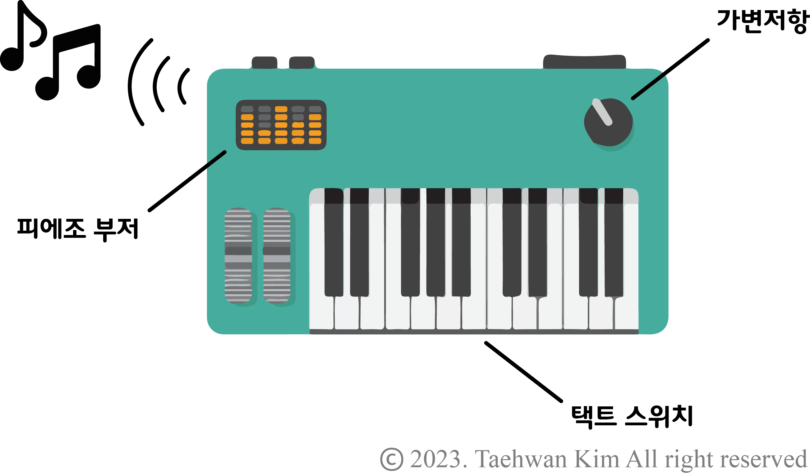
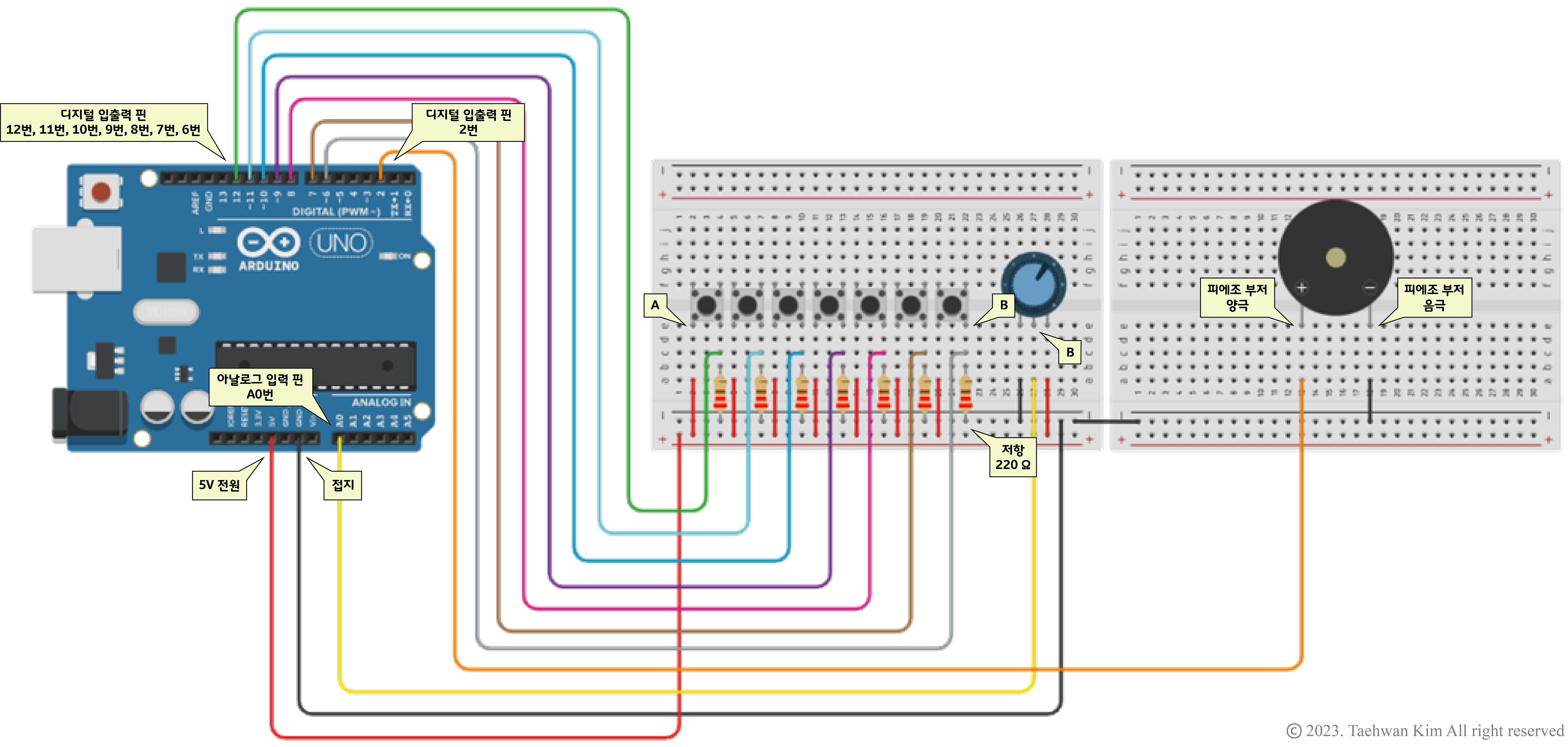
디지털 피아노 일상에서 쉽게 발견할 수 있는 디지털 피아노를 아두이노 플랫폼으로 구현해보자. 구현하고자 하는 디지털 피아노는 택트 스위치 7개와 피에조 부저, 가변저항으로 구성되어 있어, 각 스위치를 누르면 이에 해당하는 음계가 피에조 부저에서 연주된다. 또한 가변저항의 손잡이를 돌리면 옥타브를 조절할 수 있도록 프로그램을 작성해보자.
2. 프로젝트
2.1. 회로 구성

회로 구성 브레드보드용 4핀 택트스위치 6x6 breadboard friendly switch 4p [SZH-TH0018]
TACT 스위치 / DIP TYPE / 4PIN / 빵판에 바로 연결사용하는 특별한 택트스위치입니다. 부품다리가 휘어져있는 다른 제품들과 다르게 브레드보드에 알맞은 길이로 곧게 뻗어있습니다.
www.devicemart.co.kr
1/2W 1% Axial Resistor 221F (220Ω)
일반막대저항 / 탄소피막 / 1/2W / F급(±1%) / 220옴
www.devicemart.co.kr
아두이노 가변 저항 10KΩ (다이얼 타입)
10K옴 / 싱글턴 가변저항 포텐션미터 너트 와샤 포함 , 일반 가변 저항과 달리 돌리면 틱틱틱 걸리는 느낌이 있는 다이얼 타입의 저항 입니다. 일반 가변저항은 돌리면 저항감이 없어서 조정하는
www.devicemart.co.kr
IMT12D2001AP
세라믹 부저 /HC12G-P series (원래 제품명) 피에조 부조 / PIEZO(DIP) / 30mA / 2048Hz / 85dB / 12mm(D)x8.5mm(H) / 수동소저 제품입니다.
www.devicemart.co.kr
2.2. 프로그램 작성
// 1옥타브 음계 주파수 정의
#define C1 33
#define D1 37
#define E1 41
#define F1 44
#define G1 49
#define A1 55
#define B1 62

// 2옥타브 음계 주파수 정의
#define C2 65
#define D2 73
#define E2 82
#define F2 87
#define G2 98
#define A2 110
#define B2 123

// 3옥타브 음계 주파수 정의
#define C3 131
#define D3 147
#define E3 165
#define F3 175
#define G3 196
#define A3 220
#define B3 247

// 4옥타브 음계 주파수 정의
#define C4 262
#define D4 294
#define E4 330
#define F4 349
#define G4 392
#define A4 440
#define B4 494

// 5옥타브 음계 주파수 정의
#define C5 523
#define D5 587
#define E5 659
#define F5 698
#define G5 784
#define A5 880
#define B5 988

// 6옥타브 음계 주파수 정의
#define C6 1047
#define D6 1175
#define E6 1319
#define F6 1397
#define G6 1568
#define A6 1760
#define B6 1976

// 7옥타브 음계 주파수 정의
#define C7 2093
#define D7 2349
#define E7 2637
#define F7 2794
#define G7 3136
#define A7 3520
#define B7 3951

// 8옥타브 음계 주파수 정의
#define C8 4186
#define D8 4699
#define E8 5274
#define F8 5588
#define G8 6272
#define A8 7040
#define B8 7902

// 정수형 배열 선언 후 디지털 핀 번호로 초기화
int Switch[] = {12, 11, 10, 9, 8, 7, 6}; // C, D, E, F, G, A, B 순서로 연결

int Buzzer = 2; // 정수형 변수 선언 후 디지털 핀 번호 2로 초기화
int Octave1[] = {C1, D1, E1, F1, G1, A1, B1}; // 정수형 배열 선언 후 1옥타브 음계 주파수로 초기화
int Octave2[] = {C2, D2, E2, F2, G2, A2, B2};
int Octave3[] = {C3, D3, E3, F3, G3, A3, B3};
int Octave4[] = {C4, D4, E4, F4, G4, A4, B4};
int Octave5[] = {C5, D5, E5, F5, G5, A5, B5};
int Octave6[] = {C6, D6, E6, F6, G6, A6, B6};
int Octave7[] = {C7, D7, E7, F7, G7, A7, B7};
int Octave8[] = {C8, D8, E8, F8, G8, A8, B8};

int Potentiometer = A0; // 정수형 변수 선언 후 아날로그 핀 번호 A0로 초기화
int value = 0; // 정수형 변수 선언 후 0으로 초기화

void setup()
{
  for (int i = 0; i < 7; i++)
  {
    pinMode(Switch[i], INPUT); // 디지털 i번 핀을 입력(INPUT) 모드로 설정
  }
  pinMode(Buzzer, OUTPUT); // 디지털 2번 핀을 출력(OUTPUT) 모드로 설정
  pinMode(Potentiometer, INPUT); // 아날로그 A0번 핀을 출력(INPUT) 모드로 설정
}

void loop()
{
  // 아날로그 A0번 핀으로부터 받은 아날로그 신호값을 변수에 저장
  value = analogRead(Potentiometer);

  // 1옥타브 연주
  if(value >= 0 && value < 127) // 변수에 저장된 값이 0 이상 128 미만일 경우 실행
  {
    if (WhichSwitch() > -1) // WhichSwitch() 함수가 리턴한 값이 -1보다 클 경우 실행
    {
      tone(Buzzer, Octave1[WhichSwitch()]); // 디지털 2번 핀에 WhichSwitch() 함수가 리턴한 값에 해당하는 1옥타브 음계 주파수 신호 출력
    }
    else
    {
      noTone(Buzzer); // 디지털 2번 핀에 디지털 신호 미출력
    }
  }
  // 2옥타브 연주
  else if(value >= 128 && value < 255)
  {
    if (WhichSwitch() > -1)
    {
      tone(Buzzer, Octave2[WhichSwitch()]);
    }
    else
    {
      noTone(Buzzer);
    }

  }
  // 3옥타브 연주
  else if(value >= 256 && value < 383)
  {
    if (WhichSwitch() > -1)
    {
      tone(Buzzer, Octave3[WhichSwitch()]);
    }
    else
    {
      noTone(Buzzer);
    }

  }
  // 4옥타브 연주
  else if(value >= 384 && value < 511)
  {
    if (WhichSwitch() > -1)
    {
      tone(Buzzer, Octave4[WhichSwitch()]);
    }
    else
    {
      noTone(Buzzer);
    }

  }
  // 5옥타브 연주
  else if(value >= 512 && value < 639)
  {
    if (WhichSwitch() > -1)
    {
      tone(Buzzer, Octave5[WhichSwitch()]);
    }
    else
    {
      noTone(Buzzer);
    }

  }
  // 6옥타브 연주
  else if(value >= 640 && value < 767)
  {
    if (WhichSwitch() > -1)
    {
      tone(Buzzer, Octave6[WhichSwitch()]);
    }
    else
    {
      noTone(Buzzer);
    }

  }
  // 7옥타브 연주
  else if(value >= 768 && value < 895)
  {
    if (WhichSwitch() > -1)
    {
      tone(Buzzer, Octave7[WhichSwitch()]);
    }
    else
    {
      noTone(Buzzer);
    }
  }
  // 8옥타브 연주
  else
  {
    if (WhichSwitch() > -1)
    {
      tone(Buzzer, Octave8[WhichSwitch()]);
    }
    else
    {
      noTone(Buzzer);
    }
  }
}


// 어느 스위치가 눌렸는지 판별하는 함수
int WhichSwitch()
{
  int Index = -1; // 정수형 변수 선언 후 -1로 초기화
  for (int i = 0; i < 7; i+)
  {
    if(digitalRead(Switch[i]) == HIGH) // 디지털 i번 핀으로부터 받은 디지털 신호가 HIGH일 경우 실행
    {
      Index = i; // 눌린 스위치에 해당하는 음계 주파수 인덱스 저장
    }
  }
  return Index; // 음계 주파수 인덱스 리턴
}
[함께 읽으면 좋은 페이지]
아두이노 | 가변저항
1. 가변저항 저항값을 임의로 바꿀 수 있는 물리 소자이다. 극성이 없는 3개의 단자를 가지고 있으며, 손잡이를 돌리면 각 단자 사이의 저항값을 조절할 수 있다. 손잡이를 시계방향으로 돌리면 A
vedacube.tistory.com
아두이노 디지털 신호 입력 | 택트 스위치
1. 디지털 신호 입력 아두이노 소프트웨어에서 디지털 신호를 받을 핀을 설정하고 함수를 작성하여 아두이노 하드웨어에 업로드하면, 앞서 설정한 핀을 통해 디지털 신호를 입력 받을 수 있다.
vedacube.tistory.com
아두이노 | 피에조 부저
1. 피에조 부저 압전 효과(piezoelectric effect)는 수정이나 세라믹 같은 결정체에 압력을 가했을 때 전압이 발생하는 현상이다. 반대로 결정체에 전압을 가하면 물리적인 변형을 일으킬 수 있는데,
vedacube.tistory.com
반응형'Technology > Arduino' 카테고리의 다른 글
아두이노 | 초음파센서 모듈 HC-SR04 (1) 2023.11.24 아두이노 프로젝트 | 젤다의 전설 시간의 오카리나 (0) 2023.11.17 아두이노 | 피에조 부저 (1) 2023.11.03 아두이노 프로젝트 | 밝기 조절이 가능한 스탠드 (0) 2023.09.01 아두이노 | 가변저항 (0) 2023.08.25